GENERAL
1.01 SUMMARY
A. This section includes: [Manual] or [Electric] operated, automatic closing, Windstorm Resistant Overhead Rolling Fire Door.
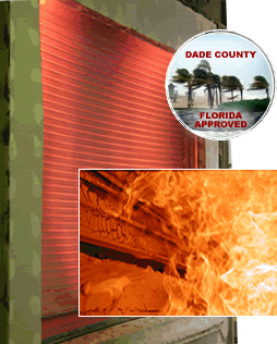
1. Successfully tested by Architectural Testing Institute (ATI) under Dade County protocols PA 201, PA 202, and PA 203 for a design load of + 60 psf.
2. Provide doors with Underwriter’s Laboratories, Inc. (UL) and Underwriter’s Laboratories of Canada (ULC) label for the fire rating classification. [4 hr.], [3 hr.], [1 ½ hr.], or [3/4 hr.] UL and ULC approved doors to be in accordance with both fire and windstorm resistant standards.
3. Design doors to withstand a windload of + 60 psf, 1.5 safety rating (Dade County equivalent to a normal +90 psf rating) for doors up to 20’8” x 30’. Provide compatible analysis certified by a Florida professional engineer for doors over 20’8” x 30’.
4. Manufacturer must be capable of providing certified Net Vertical and Net Horizontal reaction forces imposed on door jambs.
5. Quality manufacturer listed by the Texas Department of Insurance’s Windstorm Resistant Construction Guide and the Texas Windstorm Insurance Association Building Code for Windstorm Resistant Construction.
6. Cycle life: Design doors of standard construction for normal use of 10,000 cycles standard [up to 400,000 cycles].
7. Automatically resetable drop out mechanism with optional release devices. (For manually resetable doors see specs for Fire-Storm®)
8. Doors are fully spring-balanced in all models.
B. Related Sections: Related to this section, but not limited to, the following (based on Master Format 2004):
1. Section 01660 – Product Storage and Handling Requirements.
2. Section 04220 – Concrete Unit Masonry.
3. Section 05120 – Structural Steel.
4. Section 06100 – Rough Carpentry.
5. Section 08310 – Access Doors and Panels.
6. Section 08710 – Door Hardware.
7. Section 09290 – Gypsum Board.
8. Section 09900 – Paints and Coatings.
9. Section 26000 – Electrical.
10. Section 28310 – Fire Detection and Alarm.
1.02 REFERENCES
A. ASTM A 653/A 653M – Standard Specification for Steel Sheet, Zinc-Coated (Galvanized) or Zinc-Iron Alloy-Coated (Galvannealed) by the Hot-Dip Process
B. ASTM A 36 – Standard Specification for Carbon Structural Steel, Hot Rolled Steel
C. ASTM A 123 – Standard Specification for Zinc (Hot-Dip Galvanized) Coatings on Iron and Steel Products
D. ASTM A 312 – Standard Specification for Seamless, Welded, and Heavily Cold Worked Austenitic Stainless Steel Pipes
E. ASTM A 240 – Standard Specification for Chromium and Chromium-Nickel Stainless Steel Plate, Sheet, and Strip for Pressure Vessels and for General Applications
F. ASTM A 276 – Standard Specification for Stainless Steel Bars and Shapes
G. ASTM A 31 – Standard Specification for Steel Rivets and Bars for Rivets, Pressure Vessels
H. ASTM A 449 – Standard Specification for Quenched and Tempered Steel Bolts and Studs
I. ASTM E 330 – Standard Test Method for Structural Performance of Exterior Windows, Doors, Skylights and Curtain Walls by Uniform Static Air Pressure Difference
J. Dade County PA-201, PA-202, PA-203: Large Missile Impact Test, Cyclic Wind Pressure Test, and Uniform Static Air Pressure Test
K. ASCE 7-93 – Standard Minimum Design Loads on Buildings and Other Structures
1.03 SUBMITTALS
A. Submit under provisions of Section 01300.
B. Product Data: Provide manufacturer’s standard details and catalog data. Provide installation instructions.
C. Shop Drawings: Furnish shop drawings for architect’s approval. Include elevation, sections, and details indicating dimensions, materials, finishes, conditions for anchorage and support of each door
D. Submit manufacturer’s recommended operation, troubleshooting, and maintenance instructions.
1.04 QUALITY ASSURANCE
A. Manufacturer: Rolling doors shall be manufactured by a firm with a minimum of five years experience.
B. Fire-Rated Assemblies: Provide all doors with fire resistance rating required to comply with governing regulations which are inspected, tested, listed and labeled by UL, complying with NFPA 80 for class of opening. Provide UL label permanently fasted to each fire door assembly. Door shall be tested under UL10B and ULC10B, and provided with a [4 hour] [3 hr.] [1 ½ hr.] [3/4 hr.] rating. Also Factory Mutual and NY MEA approved.
C. Single-Source Responsibility: Manufacturer shall provide doors, tracks, motors, and accessories for each type of door. Secondary components shall come from a source acceptable to the manufacturer of the primary components.
1.05 DELIVERY, STORAGE, AND HANDLING
A. Deliver materials in original packaging supplied by manufacturer with intact labels. Store materials away from harmful environmental conditions and construction.
1.06 WARRANTY
A. Door Warranty: Provide one year written warranty from date of installation against deficiencies due to defects in materials or workmanship. Installer agrees to repair or replace any defects in materials or workmanship.
B. Project Warranty: Refer to Conditions of the Contract for project warranty provisions.
PART 2 – PRODUCTS
2.01 MANUFACTURER
A. Manufacturer: Alpine Overhead Doors, Inc.; 8 Hulse Road Suite 1S, East Setauket, NY 11733. Telephone 800-257-4634 or 631-473-9300. Fax 631-642-0800.
B. Model: AUTO FIRE-STORM® Windstorm Resistant Rolling Fire Door
2.02 MATERIALS
A. Curtain:
1. Slats: Constructed of interlocking, roll-formed 2 ¾” flat slats. (For insulated slats see specs for Fire-Storm® IMB)
a) Material:
i) Galvanized steel, G90 coating exterior (G60 interior), Structural Quality Grade C, as per ASTM A 653/ A 653 M
Finish: Galvanized [Powder coated] [Baked enamel] (Minimum coating conforming with Coating Designation G-01 is required)
– OR –
ii) ASTM 240 Stainless steel 300 series
Finish: [Mill finish #2B] [#4 satin finish]
b) Gauge: (Per manufacturer’s standard)
i) Doors up to 20’8” wide: Minimum 21 gauge as manufacturer standard [20, 18, 16 gauge].
ii) Doors up to 12’ wide: Minimum 22 gauge [20, 18, 16]
2. Endlocks and Windlocks:
a) Ductile cast iron, hot-dipped, galvanized endlocks riveted to each end of each slat with four Semi-tubular, Mushroom Head ¼” rivets to prevent lateral movement and to limit slat deflection and bending stress.
3. Bottom Bar: Two roll formed steel angles of minimum 2”x2”x1/8”, designed to reinforce curtain bottom. (Size dependent on dimensions per manufacturer’s standard)
a) Material:
i) Galvanized Steel as per ASTM A 653/ A 653 M
Finish: Gray shop prime [Powder Coated] [Baked Enamel]
– OR –
ii) ASTM 240 Stainless Steel 300 Series
Finish: [Mill finish #2B] [#4 satin finish]
b) Bolting:
i) 20’8” wide: ¼” bolts at 15” o.c.
ii) 12’ wide: ¼” bolts at 20” o.c.
c) Weather Stripping: Rubber astragal bolted between bottom angles (Dade County Approved).
B. Guides:
1. Guides shall be designed using structural steel angles with a minimum thickness of 3/16”, minimum 1 ¼” slotted connections, and removable bellmouth curtain stops to allow for curtain maintenance without removal of guides. Bellmouth stops shall be flush with guide groove.
a) Angles:
i) 20’8” wide: Wall angle 3 ½ x 3 ½ x 7/16”, inside angle 2 ½ x 2 ½ x 3/8”, outside angle 4 x 3 x ¼”.
ii) 12’ wide: Wall angle 2 ½ x 3 ½ x ¼”, inside angle 2 x 2 ½ x ¼”, outside angle 3 x 3 3/16” min
b) Bolting:
i) 20’8” wide: 3/8” bolts at minimum 9” o.c.
ii) 12’ wide: 3/8” bolts at minimum 15” o.c.
c) Material:
i) ASTM A 36 Carbon Structural Steel
Finish: Gray shop prime coat [ASTM A 123 Galvanized] [baked enamel paint] [powder coated].
– OR –
ii) ASTM 276 Stainless Steel 300 Series
Finish: [Mill finish #2B] [#4 finish satin]
C. Door Support Brackets and Mounting Plates:
1. Steel plate not less than 1/4” thick. Provide ball bearings at rotating support points. Bolt plates to wall mounting angles with minimum 1/2″ fasteners. Plate supports counterbalance assembly and forms end enclosures.
a) Material:
i) ASTM A 36 Carbon Steel:
Finish: Gray shop prime coat [ASTM A 123 Galvanized] [Baked enamel paint] [Powder coated].
– OR –
ii) ASTM 240 Stainless Steel 300 Series
Finish: [Mill Finish #2B]
D. Counterbalance Assembly: Torsion
1. Counterbalance assembly: Steel pipe barrel of a size capable of carrying a curtain load with a maximum deflection of 0.03” per foot of door width. Heat-treated helical torsion springs encased in a steel pipe and designed to include an overload factor of 25% to ensure minimum effort to operate. Sealed and prelubricated high speed ball bearing at rotating support points. Torsion spring charge wheel for applying spring torque and for future adjustments.
a) Material:
i) ASTM A 36 Carbon Structural Steel
Finish: Gray shop prime coat [A 123 Hot-Dip Galvanized]
– OR –
ii) A 312 Stainless Steel 300 Series
Finish: Mill finish
b) Life Cycle: High Cycle springs designed to satisfy 10m through 400m life cycles. Consult engineering if height exceeds width for any cycle above 20m. (Cycle defined as one time opening and closing of door)
E. Hood:
1. 24 gauge steel. Formed to fit the contour of the end brackets with reinforced top and bottom edges. Provide support bracing for doors wider than 20 feet at every 10 feet to prevent excessive sag. Fasten with minimum ¼” bolts at 10” o.c.
2. Shape: Hexagon [square] [round]
3. Material:
a) Galvanized Steel as per ASTM A 653/ A 653 M
Finish: [Baked enamel paint] [Powder coated]
– OR –
b) ASTM 240 Stainless Steel 300 Series:
Finish: [Mill finish #2B] [#4 satin finish]
4. [Fascia]: Galvanized [Stainless Steel], provided where areas behind door hood are open. Materials and finish same as hood.
F. Locking:
1. Provide padlockable slide locks for latching and locking door on coil side bottom bar at each jamb extending into slots in guides. (Electric Interlocks recommended with motorized doors only)
2. Manual chain hoist: Provide padlockable chain keeper on guide.
2.03 OPERATION:
A. Opening/Closing: Choose ONE type.
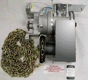
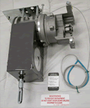
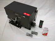
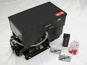
1. Redi-Reset® Industrial Duty Fire Door Operators, automatic closing motors
– OR –
2. Redi-Reset® Chain or Crank Hoist Operators (not recommended for frequently used large doors)
B. Motor Operator: Choose ONE model.
1. Model Redi-Reset® FS [NFS Also available without fail-safe] (Recommended for fire doors up to 60’ x 20’)
a) UL listed and FM approved
b) NEMA 1 enclosure rating
c) Horsepower: 1/3, 1/2, 3/4, 1 1/2, 2, 3, 5 hp
d) Phase Service: [115v single] [230v single] [208/230v three] [460v three]
e) Brake: Solenoid brake. Integral within the operator’s housing.
f) Reducer: Planetary reduction gearing and rotary limit switches.
g) Removable electrical control panel.
h) Sensing Edge: Electric [Pneumatic] [Wireless].
i) Automatic Closure shall be activated by melting of fusible link at 165º [local smoke/fire detector] [central smoke/fire alarm system]. Doors shall not require a releasing device when activated by an alarm. When automatic closure is activated, electric sensing edge and push button are inoperable.
j) Average closing speed: No less than 6” per second or more than 9” per second.
k) Fail-safe feature: In case of power failure, door shall close automatically after a 10 second delay [adjustable]
l) Each fire door shall be designed so that it may be drop tested by cutting the power, removing the fusible link, or activating alarm/smoke detector.
m) Resetting of spring tension or mechanical dropouts shall not be required. After correction cause of closure, doors shall immediately reset by opening with the push button.
– OR –
2. Model Redi-Reset® NFS (Non-Fail-Safe) (Also recommended for fire doors up to 60’ x 20’)
All features same as Model Redi-Reset® FS except for:
a) No Fail-safe feature: Door will not close automatically during power failure. Prevents unwanted closure during brief outages.
b) Each fire door shall be designed so that it may be drop tested by removing the fusible link or activating alarm/smoke detector.
– OR –
3. Model Redi-Reset® FDC (Manufactured by LiftMaster®) (Recommended for doors up to 350 sq. ft.)
a) UL listed and FM approved
b) NEMA 1 enclosure rating
c) Horsepower: ½ hp [1 hp max]
d) Phase Service: [115v single] [230v single] [208/230v three] [460v three]
e) Brake: Electromagnetic disc brake.
f) Reducer: Helical inline gear reducer, oil bath permanently lubricated, non-vented.
g) Removable PC board control panel.
h) Sensing Edge: Electric [Pneumatic] [Wireless]. Sensing edge shall be operable during all methods of closing including during a power outage. When closing during a power outage, the sensing edge shall stop door travel when an obstruction is encountered and hold the door for two seconds before releasing the door to close again.
i) Automatic Closure shall be activated by [electric thermal sensors] [fusible link] [local smoke/fire detector] [central smoke/fire alarm system]. Doors shall not require a releasing device when activated by an alarm.
j) Average closing speed: No less than 6” per second or more than 9” per second.
k) Operator shall have an internal battery backup that prevents fail-safe closing for 72 hours after power outage. Backup system shall monitor fusible link and alarm signals and initiate automatic closing upon any alarm.
l) Each operator shall be provided with a key test station to test automatic closing of the fire door. Key test station shall also include a low battery indicator.
m) Resetting of spring tension or mechanical dropouts shall not be required. After correction cause of closure, doors shall immediately reset by opening with the push button.
– OR –
4. Model Redi-Reset® FDCL (Manufactured by LiftMaster®) (Recommended for doors up to 150 sq. ft.)
a) UL listed and FM approved
b) NEMA 1 enclosure rating
c) Horsepower: ½ hp
d) Phase Service: [115v single] [230v single] [208/230v three] [460v three]
e) Brake: Electromagnetic disc brake.
f) Reducer: Spurgear/sprocket and chain reduction gearing with rotary limit switch and logic control.
g) Removable PC board control panel.
h) Sensing Edge: Electric [Pneumatic] [Wireless]. Sensing edge shall be operable during all methods of closing including during a power outage. When closing during a power outage, the sensing edge shall stop door travel when an obstruction is encountered and hold the door for two seconds before releasing the door to close again.
i) Automatic Closure shall be activated by [electric thermal sensors] [fusible link] [local smoke/fire detector] [central smoke/fire alarm system]. Doors shall not require a releasing device when activated by an alarm.
j) Average closing speed: No less than 6” per second or more than 9” per second.
k) Operator shall have an internal battery backup that prevents fail-safe closing for at least two hours after power outage. Backup system shall monitor fusible link and alarm signals and initiate automatic closing upon any alarm.
l) Each operator shall be provided with a key test station to test automatic closing of the fire door. Key test station shall also include a low battery indicator.
m) Resetting of spring tension or mechanical dropouts shall not be required. After correction cause of closure, doors shall immediately reset by opening with the push button.
C. Manual Operators:
1. Redi-Reset® II Chain
a) Manual combination chain/controlled closing system.
b) For use on doors up to 30’ x 24’ that do not require daily convenience of motor. Recommended for fire doors with exposed guides or fire doors in excess of 12’.
c) Endless steel chain, geared reduction unit, chain keeper and combination close operation/automatic drop test cable.
d) Locking mechanism to hold door at any position of travel during normal door operation.
e) Governor to control automatic closing speed.
f) Automatic Closure shall be activated by fusible link [local smoke/fire detector] [central smoke/fire alarm system]. Doors shall not require a releasing device when activated by an alarm.
g) Average closing speed: No less than 6” per second or more than 9” per second.
h) Resetting of spring tension or mechanical dropouts shall not be required.
– OR –
2. Redi-Reset® II Crank
a) Manual combination crank/controlled closing system.
b) For use on doors up to 30’ x 12’ that do not require daily convenience of motor. Recommended for finished or recessed doors.
c) Removable hand crank, geared reduction unit, and combination close operation/automatic drop test cable.
d) All other features same as Redi-Reset® II Chain.
2.03 Mounting:
1. Interior face mounted on prepared opening.
2. Interior mounted between jambs and under lintel in a prepared opening.
3. Exterior face mounted on prepared opening.
2.04 Fire Ratings:
1. Underwriter’s Laboratories:
Doors are constructed to conform within requirements specified by Underwriters Laboratories, Inc. (UL) and Underwriter’s Laboratories of Canada (ULC). Doors are automatic and self-closing, Class (A) (B) (C) (D) or oversized certificate.
4 hour – Approved for doors with openings not exceeding 162 sq. ft. in area.
Class (A) – 3 hour approved for doors in dividing fire walls with openings not exceeding 120 sq. ft. in area
Class (B) – 1 ½ hour approved for doors, in vertical shaft openings not exceeding 120 sq. ft. in area.
Class (C) – ¾ hour approved for doors in corridor or room-partition opening not exceeding 120 sq. ft. in area.
Class (D) – 1 ½ hour approved for doors in exterior wall opening not exceeding 120 sq. ft. in area.
The oversize Certificate is authorized for rolling steel doors for the protection of openings in fire walls, vertical shafts, and exterior walls where the area exceeds 120 square ft., or for openings in the above locations when width or height exceeds 12 ft. The maximum dimensions for doors for standard fire protection provided with the Oversize Door Certificate are not to exceed 56 ft. in width and 24 ft. in height.
2. Factory Mutual.
3. New York Materials, Equipment and Acceptance Division (MEA).
PART 3 – EXECUTION
3.01 EXAMINATION
A. Verify that dimensions are correct and project conditions are in accordance with manufacturer’s installation instructions; do not proceed with installation until unacceptable conditions have been corrected.
3.02 INSTALLATION
A. Install units in accordance with manufacturer’s instructions.
B. Ensure that units are installed plumb and true, free of warp or twist, and within tolerances specified by manufacturer for smooth operation.
C. Preparation for opening and installation of fire door to be in strict compliance with NPFA-80.
3.03 FIELD TESTING
A. Test doors for regular operation and automatic closing. Proper authorities having jurisdiction must witness test and sign Drop Test Form.
3.04 DEMONSTRATION
A. Instruct the Owner’s personnel in correct operation and maintenance of units.
3.05 ADJUST AND CLEAN
A. Clean units in accordance with manufacturer’s instructions.
B. Restore slight blemishes in finishes in accordance with manufacturer’s instructions to match original finish. Remove and provide new units where repairs are not acceptable to the Architect.
